GNS3で、仮想ネットワーク環境を構築しよう-6
お疲れさまです。ニックネーム たいちょう です。
第6日目ですね。前回は、wireshark でパケットをキャプチャしてみました。GNS3は色々と便利な機能満載ですね。好きなトポロジを試せる可能性を感じています。
今日は、vlan を構築してvlan間ルーティングに挑戦してみようと思います。
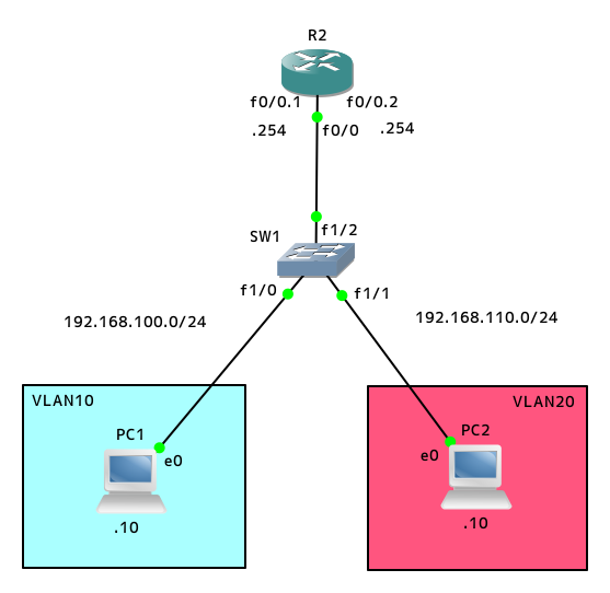
このトポロジーは、「ルーター・オン・ア・スティック」といいます。
図を見るとわかりますが、ルータに棒が刺さっているようですよね。
発音は、「ラウターオナスティッ」という感じですね。
c3600 をドラッグ&ドロップします。
ここで、NM-16ESWモジュールをスロットから追加します。
名前は、SW1 に変え、イメージもスイッチにしておきます。
スタート後、コンソールを立ち上げます。
VPCには、IPアドレス、ゲートウェイを設定し、設定を save で保存します。
では、vlan の設定に入ります。
GNS3においてvlanを作成するには、次のコマンドを打つ必要があります。
SW1# vlan database
SW1(vlan)#
この状態から、vlan を作成します。
SW1(vlan)# vlan 10
SW1(vlan)# vlan 20
確認します。
SW1(vlan)# exit
確認のコマンドですが、GNS3では、以下のようです。
SW1# sh vlan-switch
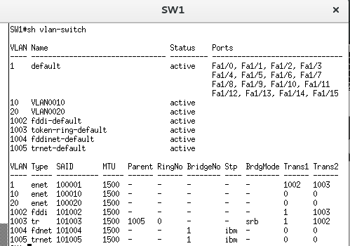
vlan10 と vlan20 ができています。
SW1# conf t
SW1(config)# int fa1/0
SW1(config-if)# switchport mode access
SW1(config-if)# switchport access vlan 10
SW1(config-if)# end
SW1# conf t
SW1(config)# int fa1/1
SW1(config-if)# switchport mode access
SW1(config-if)# switchport access vlan 20
SW1(config-if)# end
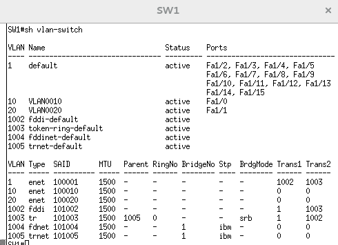
もう一度確認します。
SW1# sh vlan-switch
それぞれのポートも確認してみましょう。
SW1# sh int fa1/0 switchport
以下のように出ています。
Name: Fa1/0
Switchport: Enabled
Administrative Mode: static access
Operational Mode: static access
Administrative Trunking Encapsulation: native
Negotiation of Trunking: Disabled
Access Mode VLAN: 1 (default)
Trunking VLANs Enabled: ALL
Trunking VLANs Active: 10
Priority for untagged frames: 0
Override vlan tag priority: FALSE
Voice VLAN: none
Appliance trust: none
fa1/1 も同様に確認します。
(省略)
fa1/2 をトランクモードにします。
SW1# conf t
SW1(config)# int fa1/2
SW1(config-if)# switchport mode trunk
SW1(config-if)# end
確認します。
SW1# sh int trunk
Port Mode Encapsulation Status Native vlan
Fa1/2 on 802.1q trunking 1
Port Vlans allowed on trunk
Fa1/2 1-1005
Port Vlans allowed and active in management domain
Fa1/2 1,10,20
Port Vlans in spanning tree forwading state and not pruned
Fa1/2 1,10,20
設定できているようです。
このコマンドでも確認します。
SW1# sh int fa1/2 switchport
Name: Fa1/2
Switchport: Enabled
Administrative Mode: trunk
Operational Mode: trunk
Administrative Trunking Encapsulation: dot1q
Operational Trunking Encapsulation: dot1q
Negotiation of Trunking: Disabled
Access Mode VLAN: 0 (Inactive)
Trunking Native Mode VLAN: 1 (default)
Trunking VLANs Enabled: ALL
Trunking VLANs Active: 1,10,20
Priority for untagged frames: 0
Override vlan tag priority: FALSE
Voice VLAN: none
Appliance trust: none
ここで、もう一度以下のコマンドを打ってみます。
SW1# sh vlan-switch
default vlan 1 から Fa1/2 がトランクポートになったために消えています。
このポートを、ルータにつなげて、VLAN間ルーティングしてみます。
ルータのポートを、logical interfaces(論理インターフェース)に分割する必要があります。
これは、subinterfaces と呼ばれます。
以下の設定では、
encapsulation dot1Q <VLAN ID>
と、末尾に要求される数字は、VLAN ID を入力します。
要すれば、VLAN ID をSWITCH のVLAN ID と合わせます。
R2# conf t
R2(config)# int fa0/0.1
R2(config-subif)# encapsulation dot1Q 10
R2(config-subif)# exit
R2(config)#
同様に、fa0/0.2 を 設定します。
R2(config)# int fa0/0.2
R2(config-subif)# encapsulation dot1Q 20
R2(config-subif)# exit
R2(config)# int fa0/0.1
R2(config-subif)# ip address 192.168.100.254 255.255.255.0
R2(config-subif)# no shut
R2(config-subif)# exit
R2(config)# int fa0/0.2
R2(config-subif)# ip address 192.168.110.254 255.255.255.0
R2(config-subif)# no shut
R2(config-subif)# exit
R2(config)# int fa0/0
R2(config)# no shut
R2(config)# end
確認します。
R2# sh int fa0/0.1
上がっていますね。
同様に、fa0/0.2 も確認しましょう。
設定を保存します。
R2# copy run start
PC1 と PC2 からそれぞれにping を打ってみます。
繋がったようです。
同じスイッチに接続されているネットワークの異なる端末同士で ping が通りました。
お疲れさまです。第6日目の終了です。

