GNS3 活用 - Cisco スイッチFHRP 編 その2(Layer を考慮した構築を)
お疲れさまです。ニックネーム たいちょう です。
前回やってみたFHRPのうちのHSRPですが、VLANを収容した形にしてみたいと思います。
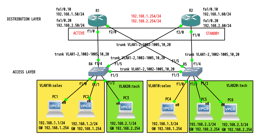
今回のトポロジは、この図のようになります。

GNS3でVLANを実行するには、多少コツがいります。
ここを参考にします。
https://www.gns3.com/discussions/save-vlan-database
Configure - Memories and disks -
PCMCIA disk0: 32 MiB
PCMCIA disk1: 32 MiB
"Automatically delete NVRAM and files" のチェックを外します。
OK をクリックします。
R4#erase flash:
Erasing the flash filesystem will remove all files! Continue? [confirm]
Erasing device... eeeeeeeeeeeeeeeeeeeeeeeeeeeeeeeeeeeeeeeeeeeeeeeeeeeeeeeeeeeeeeeeeeeeeeeeeeeeeeeeeeeeeeeeeeeeeeeeeeeeeeeeeeeeeeeeeeeeeeeeeeeeeeeeeeeeeeeeeeeeeeeeeeeeeeeeeeeeeeeeeeeeeeeeeeeeeeeeeeeeeeeeeeeeeeeeeeeeeeeeeeeeeeeeeeeeeeeeeeeeeeeeeeeeeeeeeeeeeeeeeeeeeeeeeeeeeeeeeeeeeeeeeeeeeeeeeeeeeeeeeeeeeeeeeeeeeeeeeeeeeeeeeeeeeeeeeeeeeeeeeeeeeeeeeeeeeeeeeeeeeeeeeeeeeeeeeeeeeeeeeeeeeeeeeeeeeeeeeeeeeeeeeeeeeeeeeeeeeeeeeeeeeeeeeeeeeeeeeeeeeeeeeeeeeeeeeeeeeeeeeeeeeeeeeeeeeeeeeeeeeeeeeeeeeeeeeeeeeeeeeeeeeeeeeeeeeeeeeeeeeeeeeeeeeeee ...erased
Erase of flash: complete
R4#squeeze flash:
Squeeze operation may take a while. Continue? [confirm]
Squeeze of flash complete

R4#conf t
R4(config)#vtp file nvram:vlan.dat
Setting device to store VLAN database at filename nvram:vlan.dat.

R4(config)#do dir nvram:
Directory of nvram:/

   53  -rw-        1393                    <no date>  startup-config
   54  ----          24                    <no date>  private-config
    1  ----          15                    <no date>  persistent-data
    2  ----           4                    <no date>  rf_cold_starts
    3  -rw-           0                    <no date>  ifIndex-table
    4  -rw-         720                    <no date>  vlan.dat

57336 bytes total (51771 bytes free)

R4(config)# end
R4# write memory
Building configuration...
[OK]
Access Layer のスイッチから設定していきます。
過去のブログを参考にします。
https://www.miraclelinux.com/tech-blog/ubl1rr
R4# vlan database
R4(vlan)# vlan 10 name sales
VLAN 10 added:
    Name: sales
R4(vlan)# vlan 20 name tech
VLAN 20 added:
    Name: tech
R4(vlan)#exit
APPLY completed.
Exiting....
R4#sh vlan-switch

VLAN Name                             Status    Ports
---- -------------------------------- --------- -------------------------------
1    default                          active    Fa1/0, Fa1/1, Fa1/2, Fa1/3
                                                Fa1/4, Fa1/5, Fa1/6, Fa1/7
                                                Fa1/8, Fa1/9, Fa1/10, Fa1/11
                                                Fa1/12, Fa1/13, Fa1/14, Fa1/15
10   sales                            active
20   tech                             active
1002 fddi-default                     act/unsup
1003 token-ring-default               act/unsup
1004 fddinet-default                  act/unsup
1005 trnet-default                    act/unsup

VLAN Type  SAID       MTU   Parent RingNo BridgeNo Stp  BrdgMode Trans1 Trans2
---- ----- ---------- ----- ------ ------ -------- ---- -------- ------ ------
1    enet  100001     1500  -      -      -        -    -        1002   1003
10   enet  100010     1500  -      -      -        -    -        0      0
20   enet  100020     1500  -      -      -        -    -        0      0
1002 fddi  101002     1500  -      -      -        -    -        1      1003
1003 tr    101003     1500  1005   0      -        -    srb      1      1002
1004 fdnet 101004     1500  -      -      1        ibm  -        0      0
1005 trnet 101005     1500  -      -      1        ibm  -        0      0

R4#wri mem
Building configuration...
[OK]
R4#sh ip int bri
Interface                  IP-Address      OK? Method Status                Protocol
FastEthernet0/0            unassigned      YES NVRAM  administratively down down
FastEthernet0/1            unassigned      YES NVRAM  administratively down down
FastEthernet1/0            unassigned      YES unset  up                    up
FastEthernet1/1            unassigned      YES unset  up                    up
FastEthernet1/2            unassigned      YES unset  up                    up

R4#conf t
Enter configuration commands, one per line.  End with CNTL/Z.
R4(config)#int fa1/0
R4(config-if)#switchport ?
  access    Set access mode characteristics of the interface
  mode      Set trunking mode of the interface
  priority  Set 802.1p priorities
  trunk     Set trunking characteristics of the interface
  voice     Voice appliance attributes
  <cr>

R4(config-if)#switchport mode ?
  access  Set trunking mode to ACCESS unconditionally
  trunk   Set trunking mode to TRUNK unconditionally

R4(config-if)#switchport mode access ?
  <cr>

R4(config-if)#switchport mode access
R4(config-if)#switchport access ?
  vlan  Set VLAN when interface is in access mode

R4(config-if)#switchport access vlan ?
  <1-4094>  VLAN ID of the VLAN when this port is in access mode

R4(config-if)#switchport access vlan 10

R4(config-if)#int fa1/1

R4(config-if)#int fa1/1
R4(config-if)#switchport mode access
R4(config-if)#switchport access vlan 10
R4(config-if)#int fa1/2
R4(config-if)#switchport mode access
R4(config-if)#switchport access vlan 20

R4#sh vlan-switch

VLAN Name                             Status    Ports
---- -------------------------------- --------- -------------------------------
1    default                          active    Fa1/3, Fa1/4, Fa1/5, Fa1/6
                                                Fa1/7, Fa1/8, Fa1/9, Fa1/10
                                                Fa1/11, Fa1/12, Fa1/13, Fa1/14
                                                Fa1/15
10   sales                            active    Fa1/0, Fa1/1
20   tech                             active    Fa1/2
1002 fddi-default                     act/unsup
1003 token-ring-default               act/unsup
1004 fddinet-default                  act/unsup
1005 trnet-default                    act/unsup

VLAN Type  SAID       MTU   Parent RingNo BridgeNo Stp  BrdgMode Trans1 Trans2
---- ----- ---------- ----- ------ ------ -------- ---- -------- ------ ------
1    enet  100001     1500  -      -      -        -    -        1002   1003
10   enet  100010     1500  -      -      -        -    -        0      0
20   enet  100020     1500  -      -      -        -    -        0      0
1002 fddi  101002     1500  -      -      -        -    -        1      1003
1003 tr    101003     1500  1005   0      -        -    srb      1      1002
1004 fdnet 101004     1500  -      -      1        ibm  -        0      0
1005 trnet 101005     1500  -      -      1        ibm  -        0      0

R4(config-if)#end
R4#wri mem
Building configuration...
[OK]
R5 においても図のとおりに、同様に設定します。
図をもう一度確認します。
R5のvlanは、以下のようになりました。
R5#sh vlan-switch

VLAN Name                             Status    Ports
---- -------------------------------- --------- -------------------------------
1    default                          active    Fa1/3, Fa1/4, Fa1/5, Fa1/6
                                                Fa1/7, Fa1/8, Fa1/9, Fa1/10
                                                Fa1/11, Fa1/12, Fa1/13, Fa1/14
                                                Fa1/15
10   sales                            active    Fa1/0
20   tech                             active    Fa1/1, Fa1/2
1002 fddi-default                     act/unsup
1003 token-ring-default               act/unsup
1004 fddinet-default                  act/unsup
1005 trnet-default                    act/unsup

VLAN Type  SAID       MTU   Parent RingNo BridgeNo Stp  BrdgMode Trans1 Trans2
---- ----- ---------- ----- ------ ------ -------- ---- -------- ------ ------
1    enet  100001     1500  -      -      -        -    -        1002   1003
10   enet  100010     1500  -      -      -        -    -        0      0
20   enet  100020     1500  -      -      -        -    -        0      0
1002 fddi  101002     1500  -      -      -        -    -        1      1003
1003 tr    101003     1500  1005   0      -        -    srb      1      1002
1004 fdnet 101004     1500  -      -      1        ibm  -        0      0
1005 trnet 101005     1500  -      -      1        ibm  -        0      0
PC の設定をします。
PC1> ip 192.168.1.1/24 192.168.1.254Checking for duplicate address...
PC1 : 192.168.1.1 255.255.255.0 gateway 192.168.1.254

PC1> save
Saving startup configuration to startup.vpc
.  done

PC1> sh ip

NAME        : PC1[1]
IP/MASK     : 192.168.1.1/24
GATEWAY     : 192.168.1.254
DNS         :
MAC         : 00:50:79:66:68:00
LPORT       : 10004
RHOST:PORT  : 192.168.56.1:10006
MTU:        : 1500
PC2-PC6 までも、図のとおりに同様に設定します。
PC2-PC6の設定が終了したとします。
R4とR5 の fa1/3 をトランク接続します。
R4#conf t
R4(config)#int fa1/3
R4(config-if)#switchport ?
  access    Set access mode characteristics of the interface
  mode      Set trunking mode of the interface
  priority  Set 802.1p priorities
  trunk     Set trunking characteristics of the interface
  voice     Voice appliance attributes
  <cr>

R4(config-if)#switchport trunk ?
  allowed        Set allowed VLAN characteristics when interface is in trunking
                 mode
  encapsulation  Set trunking encapsulation when interface is in trunking mode
  native         Set trunking native characteristics when interface is in
                 trunking mode

R4(config-if)#switchport trunk enc ?
  dot1q  Interface uses only 802.1q trunking encapsulation when trunking

R4(config-if)#switchport trunk enc dot1q
R4(config-if)#switchport mode trunk
R4(config-if)#switchport trunk allowed vlan 1-2,1002-1005,10,20
R4(config-if)#end
R4#sh int trun

Port      Mode         Encapsulation  Status        Native vlan
Fa1/3     on           802.1q         trunking      1

Port      Vlans allowed on trunk
Fa1/3     1-2,10,20,1002-1005

Port      Vlans allowed and active in management domain
Fa1/3     1,10,20

Port      Vlans in spanning tree forwarding state and not pruned
Fa1/3     1,10,20

R4#wri mem
Building configuration...
[OK]
R5 の fa1/3 も同様に設定します。
同じVLANに所属しているPC同士の疎通を確認します。
PC1> ping 192.168.1.2
84 bytes from 192.168.1.2 icmp_seq=1 ttl=64 time=0.194 ms
84 bytes from 192.168.1.2 icmp_seq=2 ttl=64 time=0.612 ms
84 bytes from 192.168.1.2 icmp_seq=3 ttl=64 time=0.492 ms
84 bytes from 192.168.1.2 icmp_seq=4 ttl=64 time=0.478 ms
84 bytes from 192.168.1.2 icmp_seq=5 ttl=64 time=0.453 ms

PC3> ping 192.168.2.2
84 bytes from 192.168.2.2 icmp_seq=1 ttl=64 time=0.349 ms
84 bytes from 192.168.2.2 icmp_seq=2 ttl=64 time=0.558 ms
84 bytes from 192.168.2.2 icmp_seq=3 ttl=64 time=0.511 ms
84 bytes from 192.168.2.2 icmp_seq=4 ttl=64 time=0.411 ms
84 bytes from 192.168.2.2 icmp_seq=5 ttl=64 time=0.547 ms
現在のところ、VLAN間ルーティングは実施されていません。
過去のブログを参考に、VLAN間ルーティングを実施します。
https://www.miraclelinux.com/tech-blog/egtr3j
まずは、R4 と R5 の fa1/4 をトランク接続にするのでした。
もう一度図を確認します。
R4#conf t
R4(config)#int fa1/4
R4(config-if)#switchport trunk encapsulation dot1q
R4(config-if)#switchport mode trunk
R4(config-if)#switchport trunk allowed vlan 1-2,1002-1005,10,20
R4(config-if)#end
R4#wri mem
Building configuration...
[OK]
R4#sh int tru

Port      Mode         Encapsulation  Status        Native vlan
Fa1/3     on           802.1q         trunking      1
Fa1/4     on           802.1q         trunking      1

Port      Vlans allowed on trunk
Fa1/3     1-2,10,20,1002-1005
Fa1/4     1-2,10,20,1002-1005

Port      Vlans allowed and active in management domain
Fa1/3     1,10,20
Fa1/4     1,10,20

Port      Vlans in spanning tree forwarding state and not pruned
Fa1/3     1,10,20
Fa1/4     1,10,20
R5 でも同様に設定します。
また、残りのインタフェースf1/3,f1/5もトランク接続にしておきます。
Distribution Layer のスイッチを設定します。
ルーティングするほうでは、サブインターフェースを作成するのでした。
R1 の fa1/0 にサブインタフェースを作成して、IP アドレスを設定します。
IP アドレスを設定するには、IEEE 802.1Q を設定しておく必要があります。
R1#conf t
R1(config)#int fa1/0.10
R1(config-subif)#encapsulation dot1Q 10
R1(config-subif)#ip add 192.168.1.50 255.255.255.0
R1(config-subif)#int fa1/0.20
R1(config-subif)#encapsulation dot1Q 20
R1(config-subif)#ip add 192.168.2.50 255.255.255.0
R1(config-subif)#exit
R1(config)#int fa1/0
R1(config-if)#no shut
R1(config-if)#end

R1#sh ip int bri
Interface                  IP-Address      OK? Method Status                Protocol
FastEthernet0/0            unassigned      YES NVRAM  administratively down down
FastEthernet0/1            unassigned      YES NVRAM  administratively down down
FastEthernet1/0            unassigned      YES manual up                    up
FastEthernet1/0.10         192.168.1.50    YES manual up                    up
FastEthernet1/0.20         192.168.2.50    YES manual up                    up
FastEthernet2/0            unassigned      YES unset  administratively down down
R1#wri mem
Building configuration...
[OK]
R2 のサブインタフェースには、それぞれ、192.168.1.60、192.168.2.60 を設定します。
この状態では、VLAN10 と VLAN20 の疎通はできません。GATEWAY アドレスをもつインタフェースが存在しない
からです。
それでは、ゲートウェイアドレスをもつ HSRP を設定します。
R1(config)#int fa1/0.10
R1(config-subif)#standby 1 ip 192.168.1.254
R1(config-subif)#exit
R1(config)#int fa1/0.20
R1(config-subif)#standby 2 ip 192.168.2.254
R1(config-subif)#end
*Mar  1 00:25:43.239: %HSRP-5-STATECHANGE: FastEthernet1/0.10 Grp 1 state Standby -> Active
*Mar  1 00:26:05.507: %HSRP-5-STATECHANGE: FastEthernet1/0.20 Grp 2 state Standby -> Active
R1#wri mem
Building configuration...
[OK]
---
R2(config-subif)#standby 1 ip 192.168.1.254
R2(config-subif)#exit
R2(config)#int fa1/0.20
R2(config-subif)#standby 2 ip 192.168.2.254
R2(config-subif)#end
R2#
*Mar  1 00:22:30.975: %HSRP-5-STATECHANGE: FastEthernet1/0.10 Grp 1 state Speak -> Standby
*Mar  1 00:22:49.023: %HSRP-5-STATECHANGE: FastEthernet1/0.20 Grp 2 state Speak -> Standby
R2#wri mem
Building configuration...
[OK]
VLAN1 の端末と VLAN2 の端末の疎通を確認します。
PC1> ping 192.168.2.1
192.168.2.1 icmp_seq=1 timeout
192.168.2.1 icmp_seq=2 timeout
84 bytes from 192.168.2.1 icmp_seq=3 ttl=63 time=11.887 ms
84 bytes from 192.168.2.1 icmp_seq=4 ttl=63 time=15.396 ms
84 bytes from 192.168.2.1 icmp_seq=5 ttl=63 time=14.835 ms
HSRP の状態を確認します。
R1#sh standby bri
                     P indicates configured to preempt.
                     |
Interface   Grp  Pri P State   Active          Standby         Virtual IP
Fa1/0.10    1    100   Active  local           192.168.1.60    192.168.1.254
Fa1/0.20    2    100   Active  local           192.168.2.60    192.168.2.254

R2#sh standby bri
                     P indicates configured to preempt.
                     |
Interface   Grp  Pri P State   Active          Standby         Virtual IP
Fa1/0.10    1    100   Standby 192.168.1.50    local           192.168.1.254
Fa1/0.20    2    100   Standby 192.168.2.50    local           192.168.2.254
さて、ここからがお楽しみです。
R1を停止させたらどうなるでしょうか。
確認は、次回行いましょう。
お疲れさまです。第2日目の終了です。ニックネーム たいちょう でした。
次回をお楽しみに。

